POWERPLANTS RESOURCE CENTER > GERMANY > PREVIOUS PAGE
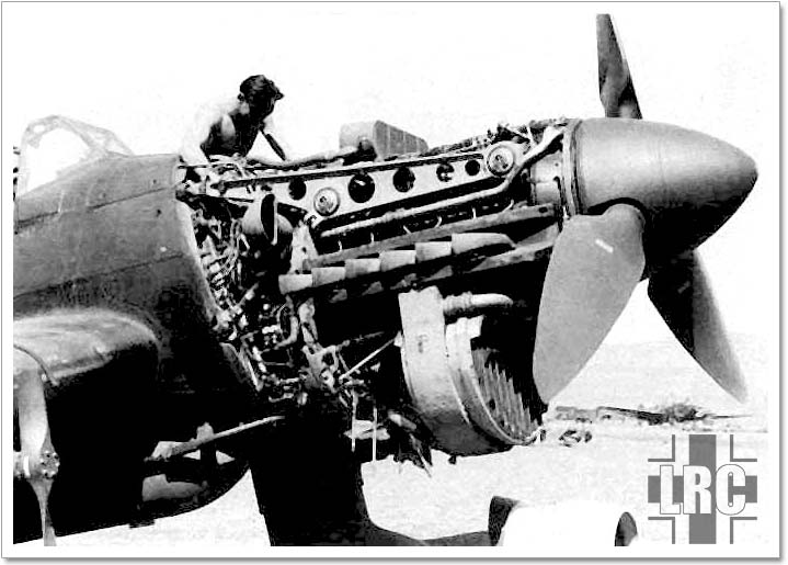
Ju 87B with Jumo 211A.
[Source: unknown]
Specifications: Jumo 211A
Type: 12 Cylinder, 60° inverted Vee. Liquid cooled with direct fuel injection.
Length (without airscrew shaft): 1,745mm (68.7 in.)
Width: 804mm (31.6 in.)
Height: 1,659mm (65.3 in.)
Weight (Dry, no fluids): 640 kg. (1,408 lbs.)
Performance:
Take-Off/Emergency power:
950 hp at 2,200 rpm at 1.2 ata at sea level.
1,000 hp at 2,200 rpm at 1.2 ata at 5,181.6 m (17,000 ft.).
Climbing:
850 hp at 2,200 rpm at 1.1 ata at sea level.
870 hp at 2,200 rpm at 1.1 ata at 5,181.6 m (17,000 ft.).
Cylinders:
|
Bore: 150mm (5.9 in.) Stroke: 165mm (6.5 in.) |
Capacity: 35 liters (2,136 Cubic Inches) Compression Ratio: 6.56:1 |
Pistons:
Forged aluminum-alloy trunk type, with three compression and two oil scraper rings, one of the latter being above the gudgeon-pin. Fully-floating gudgeon pins located by light alloy end caps spigoted with with a sliding fit into the pins.
Connecting rods:
One forked and one plain rod clamped to outer diamter of big-end bearing for each pair of cylinders. 80/20 copper/lead steel-backed big end bearings. Little-end bearings have floating cast iron bushings.
Crankshaft:
Six-throw one-piece shaft running on eight lead/bronze steal-backed bearings, the additional bearing being placed on the forward side of the airscrew reduction gear. The fourth bearing from the rear is flanged to take crankshaft end thrust. All webs are in the form of flat plates and are extended to form balance weights, the shape of each pair of webs on each side of each main bearing through holes drilled in the journels and crankpins. Short tubes are fitted internally to each hole to prevent sludge entering bearings and possibly to reduce stress in the shaft around the hole.
Crankcase:
Main case is of cast aluminum, integral with the cylinder blocks and airscrew reduction gear casing, carries the main cylinder bearings in vee diaphragms, the legs of which are tied together by ribs through which the cannon tube runs. Top cover well ribbed and attached to body by fourteen studs. Lower cover with oil strainer screend acts as oil collector from crankcase scavenging holes.
Valve gear:
Underhead camshaft with rocker-arms operating two intake and one exhaust valve per cylinder. Camshaft bearing pedastals are cast integrally with the single-piece aluminum-alloy cylinder-head. Intake valves are of chromium matensite steel. Hollow sodium-filled exhaust valves are of austenitic steel. Both valves have welded stem tips. Camshafts are on seven aluminum-iron alloy bearings, driven by level and spur gears from the lower end of the auxiliary gear box. Rockers oscillate on short spindles which are bolted to bosses on the cylinder head, thus dispensing with bearing caps. Contact between cams and rockers are on rollers.
Supercharger:
Two-Speed centrifugal supercharger mounted on starboard side of engine and driven off the rear end of the crankshaft by the main accessory drive shaft. Housing and fully shrouded impeller are magnesium-alloy forgings. A pair of bevel gears drive layshaft connected to impeller shaft by two intermediate gears. Low-ratio intermediate gear (7.85:1) couple to shaft by roller clutch. High-ratio gear (11.37:1) by mechanically operated friction clutch. Barometric capsule-operated automatic two-speed gear change operated through a hydraulic servo incorporating an automatic override to prevent opertion in high ratio below 3,050m (10,000 ft.). Barrel-type throttle with automatic boost control between supercharge and engine.
Fuel Injection:
Dual pump draws fuel from feed tank through de-aerator to Junkers 12-plunger Vee-type injection pump mounted in engine Vee by flexible metallic mountings. Plungers operated by a single camshaft driven at half engine speed by a long splined shaft from the lower end of the gear train for the oil scavenge pumps. Pressure temperature control unit. Boost pressure controlled by fully variable datum oil servo units. Single-orifice centrifugal-type injection nozzles on insides of Vee and spray horizontally across the cylinders.
Ignition:
Two Bosch high-tension magnetos, one supplying exhaust side spark plugs and the other the intake plugs. Four spark plug holes per cylinder but only two used. Spark plugs located for accesibility, being 180° apart on eight cylinders and 120° apart on remainder.
Airscrew Drive:
Plain spur type (Ratio 645.1). Both the driving and driven gears are splinned to the shafts and are centralised by split bronze cones. The driven shaft is mounted on a roller race at the rear end and a combined roller and thrust ball race at the front housing cover. The airscrew shaft is detatchable from the gear shaft, to which is is secured by face serrations and eight bolts.
Accessory Drives:
Cast aluminum accessory drive case on rear of crankcase. All drives taken from end of crankshaft through short drive-shaft and all gears have both their bearings in case so that alignment is not disturbed when case is removed. Eighteen drives include two camshafts, one generator, two magnetos, one supercharger, three oil scavenge pumps, one oil pump, one vacuum pump, one tachometer, one starter, one injection pump, one fuel pump, one coolant pump and two unsed auxiliary drives.
Lubrication:
One oil pressure and six scavenge pumps, the latter in three assemblies of two each. Double scavenge pump at rear end of each valve cover, pair of main pumps in accessory case, one at top and one at bottom. A;; pumps of straight spur-gear type. Oil flow from pressure pump and strainer assembly through cored passages to rear auxiliary drive-case abd then outward through external line to reduction gear case. A tee fitting at the approximate center of the line supplies oil to fuel injection pump and a second tee fitting forward diverts oil through two lines to camshaft housings. Internal piping within reduction gear case feeds main ceter line of crankshaft. All scavenged oil drains to bottom of the crankcase cover where it is picked up and delivered to oil coolers and tank. Outlet oil passes through disc strainer, rotation of which is supplied ratchet from throttle linkage so that any changes in throttle cleans the filter.
Applications:
|
– Avia S-199 – Heinkel He 111E, H and Z – IAR 79 – Junkers Ju 87 |
– Junkers Ju 88 – Junkers Ju 252 – Savoia-Marchetti SM.79 (Romanian variants) |
Sources:
Jane's Fighting Aircraft of World War II. London. Jane's Publishing Company, 1945/46.
POWERPLANTS RESOURCE CENTER > GERMANY > PREVIOUS PAGE